
Selection of castors for industrial situations
09 March 2011
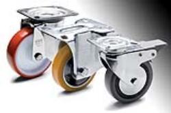
Choosing the right wheel Rather obviously any product that isn’t used under the conditions for which it was designed may not satisfy the user’s needs.
 It may also damage materials and cause injuries. In order to understand the possible pitfalls here are some examples in which wheels and castors are used incorrectly:
• using a wheel not suitable for the floor will deteriorate the wheel covering and damage the floor
• choosing a fixed castor or inappropriate configuration of castors under operating conditions for which a equipment must be very maneuverable will make it extremely difficult to move that equipment
• applying a load that exceeds the wheel’s rated load capacity can readily lead to wheel malfunctions and premature deterioration.
Therefore it is worth performing a technical analysis of the operating conditions. The most economical solution may then be chosen only after the product has been technically evaluated.
The purpose of performing a technical analysis on an equipment moving solution is to define the operating conditions and any external factors that may affect equipment use.
The following factors should be analysed in order to choose the right wheel:
• nature and condition of the ground (5.1)
• environment (5.2)
• magnitude and nature of the load (5.3)
• speed and means of traction (5.4)
• maneuverability (5.5)
• data analysis and choice (5.6)
The process of choosing the right wheel to match the operating conditions can then be divided into three steps:
Step one: identifying the correct type of wheel based on the floor and the characteristics of the operating environment.
Step two: calculating the dynamic capacity, static load and rolling resistance required by the specific application and therefore, determining the wheel diameter.
Step three: identifying the correct bracket and checking the dynamic capacity of the castor (wheel/bracket assembly).
If the evaluation of these various aspects generates different data with reference to the same wheel and/or castor characteristic, the final choice should be made based on the most conservative condition.
• Static load [N]
Static load is the maximum load that a motionless (stationary) wheel can support without generating any permanent deformations that may reduce its operating efficiency. A wheel mounted on equipment that is seldom moved and therefore almost always remains in the same position, is defined as being subjected to a static load.
• Dynamic carrying capacity
Dynamic carrying capacity of a wheel is defined as the value (expressed in N) of the maximum load that can be supported by that wheel in conformity with ISO 22883:2004 and UNI EN 12532:2001 that, for industrial wheels, require dynamic testing under the following conditions:
- constant speed of 1.1 m/s (4 km/h)
- overcoming 500 obstacles and 15,000 revolutions of the diameter
- obstacles with width 100 mm and height 5% of the wheel diameter with an elastic rolling strip (hardness up to 90 Shore A) and 2.5% of the diameter for wheels with a rigid rolling strip (hardness greater than 90 Shore A)
- temperature 20 °C (tolerance ± 10 °C)
- non-continuous operation (3 minutes of operation and 1 minute stopped)
- smooth, hard and horizontal floor.
• Rolling resistance
Rolling resistance is the value (expressed in N) of the maximum load that can be supported by each single wheel at a constant speed of 4 km/h with application of a tractive force or thrust equal to 50N (excluding the initial pickup). This value is obtained by applying a tractive force of 200N to a 4-wheeled equipment and measuring the magnitude of the maximum transportable load per wheel during normal moving conditions.
The applied tractive force of 200N complies with the international workplace standard for indoor moving and is universally recognised as the limit of human effort that can be supported for extended periods of time.
5.1 Nature and condition of the ground
The nature and condition of the ground and the presence of any obstacles will have an influence on choosing the right wheel. They are also important factors affecting the performance of the moving equipment as well as the efficiency and longevity of the wheels and castors themselves.
Special attention is required for cases involving uneven floors or where obstacles are present. In this case, the impact of the wheel against an obstacle generates resistance whose magnitude depends on the elasticity of the rolling strip material. In fact, the energy absorbed during an impact is greater in a wheel with an elastic rolling strip than in a rigid wheel, thus partially cancelling the braking effects caused by the obstacle.
For floors that are uneven or on which obstacles are present, with load capacity being equal, a wheel with a greater diameter should be chosen in order to overcome the obstacle. The wheel must be chosen very carefully in all cases in which there are obstacles, chemical and/or organic substances and machining residues. Common types of industrial flooring are:
- tiles
- asphalt
- cement-resin
- not paved floor
- expanded metal floor
- floor with chips, obstacles etc.
The main floor-wheel covering combinations available from Elesa are listed in the following table.
5.2 Environment
To choose the right wheel, it’s also important to determine if the wheel materials are compatible with the chemical-environmental conditions, the temperature, the humidity and the inductive electrostatic phenomena that may affect wheel operation.
The standard operating conditions are normally indicated in the manufacturer’s catalogue for each type of wheel.
Chemical-environmental conditions
Because there are so many different types of aggressive chemical agents in work environments, it’s difficult to provide a complete and exhaustive description.
The main chemical substances that a wheel may come in contact with include:
- weak acids (e.g. boric acid, sulphurous acid)
- strong acids (e.g. hydrochloric acid, nitric acid)
- weak bases (e.g. alkaline solutions)
- strong bases (soda, caustic soda)
- chlorinated and aromatic solvents (e.g. acetone, turpentine)
- hydrocarbons (e.g. petrol, oil, diesel oil, mineral oils)
- alcohol (e.g. ethyl alcohol)
- fresh water
- salt water
- saturated steam
Therefore, when choosing a wheel, it’s very important to check if the material forming the covering, the wheel centre body, the rolling actions and the bracket is compatible with the specific features of the operating environment. Caution is required in those sectors in which water, acids, bases, steam and other aggressive agents are often present. For example, a polyurethane wheel should be used instead of a rubber tyred wheel in environments with a large quantity of oils, fats and hydrocarbons, while it is recommended to use stainless steel castors in humid environments and in the presence of high saline concentrations.
Temperature
If operating temperatures in an application differ from the standard range of values indicated by the manufacturer then check the resistance of the wheel materials. This not only applies to the rolling strip and the wheel centre body, but also to the type of lubricant used (it may be necessary to contact the
manufacturer). For standard Elesa castors the proportions of their carrying capacity varying as a function of temperature are shown in the following table.
The above-mentioned variation values refer to the prolonged and continued use (over 30 minutes) of the wheels at the specified ambient temperatures.
5.3 Magnitude and nature of the load
The magnitude of the load is the value [N] obtained by adding the weight to be transported to the equipment weight (tare). The nature of the load, either a liquid or a solid, has a significant effect on the wheel load capacity calculation. The formula to determine the load capacity for each wheel is:
where: Q = load capacity for each wheel Pu = weight to transport Pc = equipment tare (equipment weight) n = number of wheels in contact with the ground
SOLID LOAD:
For a solid load, n=3 for a four-wheeled equipment (where three out of four wheels are considered to be in contact with the ground at all times).
LIQUID LOAD:
For a liquid load n=2 for a four-wheeled equipment (where two out of four wheels are considered to be alternatively in contact with the ground).
A thorough analysis is indispensable when the equipment is part of an automated or continuous cycle production unit. In this case, all the forces that act on the wheel must be taken into consideration; therefore, it is recommended to include appropriate allowances and safety factors.
5.4 Speed and means of traction
Equipment speed is an important factor when choosing a wheel. In fact, if the speed is 0, and thus the use is mainly static, it is enough to compare the load capacity for each wheel with the static load indicated in the manufacturers’ catalogues.
If the speed is other than 0, then the means of traction must be taken into consideration. The means of traction is the equipment used to exert the force that moves the body. In industry, traction devices can be manual or mechanical. Manual moving refers to the situation in which the force is exerted by one or more persons, while mechanical refers to the situation in which such force is exerted by a mechanical device (on-board drives or by using towing devices).
• Manual moving
For manual moving, the speed is generally less than or equal to 4 km/h.
Choosing a wheel that allows only one operator to move a load should be based on a wheel rolling resistance value determined by the following formula:
where: S = rolling resistance Pu = weight to transport Pc = equipment tare (equipment weight) n = number of equipment wheels (maximum 4) The value obtained should be compared to the wheel rolling resistance value indicated in the manufacturer’s catalogue.
• Mechanical moving with towing devices
or towed mechanical moving, the wheel should be chosen based on the equipment’s operating speed. The wheel rated dynamic load capacity normally refers to a speed of no more than 4 km/h (1.1 m/s).
If the speed is higher than 4 km/h, a correction factor must be applied to the load capacity value since the materials forming the wheel undergo chemical-physical changes during operation which lead to their performances decreasing with an increase in operating speed.
The indicative percentages of load capacity variation with an increase in speed for different types of wheels are shown in the following table.
• On-board mechanical movement
For equipment with an on-board drive (equipment with drive wheels – self-propelled), the wheels are subjected to particular stress and strain.
In fact, the drive wheels not only support the load, but also must transmit the tangential stress that allows the wheel and therefore the equipment to move. In addition, the drive wheel covering is subjected to even greater stress.
In particular, when choosing wheels and castors for self-propelled equipment, the following factors must also be taken into consideration:
• type of plain or ball bearing applied in the bore
• shaft/bore coupling tolerances
• bore material in relation to shaft material
• start and stopping frequency of the motion transmission part
• direction reversals
• presence of even temporary overloads
Since many factors have to be evaluated, it is recommended that specifiers contact ELESA (UK) Ltd. to choose the correct wheels and castors for applications involving self powered equipment.
5.5 Maneuverability
Equipment maneuverability refers to the ability of equipment to be moved more or less easily during use.
The limited space available inside some production departments or particularly winding routes that sometimes connect one work unit to another may require special equipment maneuverability characteristics to make operator tasks easier. Swivel castors allow the equipment to rotate and the greater the castor offset (i.e. the distance between the bracket rotation axis and the wheel rotation axis), the easier the rotation. However, though it does guarantee excellent maneuverability, excessive offset may cause the castor to oscillate along straight routes (Shimmy effect). Fixed castors do not allow the equipment to change direction but do guarantee directionality. In any case, the fixed castors must be mounted so that they are perfectly parallel to each other. The most common wheel layouts along with the relative castors are shown in the following table.
5.6 Choosing the wheel
Each of the parameters and operating characteristics outlined in the previous paragraphs is used in one of the three steps involved in choosing the wheel.
Step 1
The type of wheel suitable for the floor and operating environment is identified in step 1. The following graph summarizes the factors that influence the choosing of the type of wheel; “type of wheel” means: materials that form the covering and the wheel centre body; type of anchorage between covering and wheel centre body; rolling actions
Step two
The load capacity, static load and smoothness values required by the specific application and needed to determine the wheel diameter are calculated in step two. One of the most important parts of this step is an analysis of the load that the wheel must support. The following diagram indicates what calculations to perform and what values to consider depending on the various operating conditions. These aspects must always be indicated (magnitude and nature of the load and speed), while ensuring that all the values determined are not higher than the rated values indicated in the manufacturer’s catalogue. If the evaluation of any of these aspects generates different data with reference to the same wheel characteristic, the final choice must be made based on the most conservative condition.
Step three
The correct castor is chosen in the third step. The step can be divided into two separate parts:
1. Choosing fixed or swivel brackets, depending on maneuverability and directionality needs.
2. Checking the compatibility between dynamic load capacity and rated dynamic load capacity of the wheel and bracket. The following table summarizes some general indications for choosing the right wheels according to the application’s features.
Further information on Elesa (UK) Ltd products may be found at www.elesa.co.uk
Other Press Releases By This Company
- 09/04/2024 - New ELESA Vacuum Suction Cups for automation
- 07/03/2024 - ADI Design Index: selected the ELESA M.2000-SWM “Handle with monostable switch and LED indicator light”
- 08/02/2024 - Elesa Presents Visual Flow Indicators with Integrated Measurement Capabilities
- 04/01/2024 - Elesa Expands Further into ATEX-Compliant Hydraulic Components
- 09/11/2023 - Elesa Joins Forces with Experts in Material Handling, Jenco.
- 03/10/2023 - Hygienic design standard components: A new meaning to "Hygiene"
- 07/09/2023 - Vibration damping levelling feet and Super-technopolymer ball joint
- 27/04/2023 - Self-Sanitisation with Elesa Machine Components
- 03/11/2022 - ELESA protection elements - Quick and effective solutions
- 09/08/2022 - M.2000-SWM handle With electrical safety switch and LED indicator light
- 21/06/2022 - High quality ELESA magnets
- 20/06/2022 - Level bubbles
- 20/06/2022 - New MPI-R10-RF Magnetic measuring system with data transmission via radio frequency Length or angle modes
- 20/06/2022 - Modular roller tracks
- 14/06/2022 - Beauty in Engineering Solutions
- 14/06/2022 - EVH. Tubular handles oval cross section
- 14/06/2022 - Elesa solution for high temperatures
- 21/12/2021 - Elesa quality handles for commercial catering equipment
- 20/12/2021 - New industrial magnets added to Elesa range
- 02/12/2021 - New Elesa SFX series hydraulic anti-splash breather caps, plus dipstick
- 23/11/2021 - Elesa interlocked hinge protects packaging equipment
- 03/11/2021 - New Elesa connecting clamps in technopolymer for tubular frames and mountings
- 28/10/2021 - Elesa standard machine components at the Advanced Engineering Exhibition, 3-4 Nov at the NEC – stand G10
- 30/09/2021 - Elesa digital position indicators meet the time challenge for Packaging machine manufacturers
- 23/09/2021 - New Elesa stainless steel hinges in AISI 304 grade
- 03/09/2021 - New Elesa IP65 interlock handles in stainless steel and aluminium, with electronic and pneumatic pushbuttons
- 13/08/2021 - Elesa standard elements for packaging machines at the 2021 PPMA Show – Stand No. E01
- 06/08/2021 - New Elesa linear actuators for Robotics and Machine Tools
- 26/07/2021 - Elesa toggle clamps with extended lever solve the reach problem
- 12/07/2021 - New Elesa Ball Transfer Units, Roller Tracks and Conveyor Balls
- 16/06/2021 - New Elesa SAN industrial components incorporate silver ions for sanitisation against microbes, bacteria and fungi
- 15/06/2021 - Elesa extend their ESD range into castors and wheels for sensitive and hazardous areas
- 02/06/2021 - Elesa standard component manufacturing goes Green with hydroelectric and other 100% renewable power
- 18/05/2021 - Elesa MPI-R10 linear and angular magnetic measuring system – simple, accurate, reliable
- 22/04/2021 - Elesa Visual Flow Indicators - now with Flow Meter sensor
- 13/04/2021 - Elesa new CFMX hinges in high strength Supertechnopolymer
- 10/03/2021 - Elesa angled handles inclined to make things easier for many industries
- 12/02/2021 - Elesa flexible coolant hoses support many applications
- 08/02/2021 - Elesa launch new ranges of protective caps and plugs
- 21/01/2021 - Elesa launch high performance Misati pneumatic clamps for automation and robotics applications
- 20/01/2021 - Elesa establish a quality manufacturing process for industrial components and address the issue of quality in today’s industrial marketplace
- 14/01/2021 - Elesa launch high performance Misati pneumatic clamps for automation and robotics applications
- 01/12/2020 - Support for the Packaging Industry – Elesa standard components make life easier with new brochure
- 13/11/2020 - Elesa announce new wire rope arrival to vibration damper family
- 14/10/2020 - Elesa standard industrial elements support the welding equipment industry
- 12/10/2020 - Elesa standard components for machine enclosures and guards
- 16/09/2020 - Elesa new FH Modular Coolant Hose system
- 14/09/2020 - Elesa supports the Waste Management Industry with specialist standard components
- 05/08/2020 - Elesa support COVID security with screen mounting clamps for shops and industrial safety
- 03/08/2020 - New Elesa pneumatic fastening clamps speed manufacturing processes
- 15/07/2020 - Elesa High Performing Components address the needs of Process Control Industries
- 02/07/2020 - Elesa standard Ergostyle® components for the Office Equipment industry
- 04/06/2020 - Elesa – Metal and Visually Detectable components for food and pharmaceutical production lines
- 14/05/2020 - Elesa Industrial Magnets – a new take on many options for positioning, clamping and retention
- 05/05/2020 - Elesa ESD components – attractive to the spraying and powder coating industry
- 04/05/2020 - Lighting industry components - Elesa focuses on standard mounting elements
- 06/04/2020 - Elesa expand high-performing SAN (sanitary) components range for hygiene environments
- 23/03/2020 - Elesa standard components for Audio Visual Equipment
- 04/03/2020 - Elesa – New Expanded Catalogue and E-Commerce website
- 25/02/2020 - Elesa High Performing components for textile industries
- 05/02/2020 - Elesa announces production industry service focus on the Furniture Industry
- 13/01/2020 - Elesa at Southern Manufacturing & Electronics 2020
- 19/12/2019 - External hinges from Elesa – enclosure doors to equipment safety cut-off
- 09/12/2019 - Elesa open the door for Newgate Secure Access Solutions
- 03/12/2019 - Stainless steel from Elesa – synonymous with quality - catalogue supplement
- 12/11/2019 - Expanding machine element range from Elesa - new catalogue supplement
- 24/10/2019 - WestRock Linkx Systems and Elesa reduce packaging machine change over times – reduce errors - giving repeatable savings
- 14/10/2019 - Elesa Indicators – a story of quality
- 27/09/2019 - Elesa – standard elements at the Advanced Engineering Exhibition, NEC, 30-31 October, Stand No. A2
- 06/09/2019 - Elesa at PPMA Exhibition, 1-3 October @ NEC, Stand No. E03
- 22/08/2019 - Elesa unique Ergostyle® design – a market responsive approach
- 08/08/2019 - Elesa RE series castors and wheels offer broad range of types and materials for industrial purposes
- 29/07/2019 - Elesa levelling feet match industrial applications and aggressive environments
- 17/07/2019 - Elesa ZCR and ZCL modular transmission elements – racks and spur gears
- 19/06/2019 - ELECOLOR® machine tool components
- 29/05/2019 - Elesa save Aquaflame time and money – and ease production issues
- 09/05/2019 - Elesa roller tracks make moving the load easy
- 24/04/2019 - Elesa clamps facilitate sensor and equipment mounting systems
- 04/04/2019 - Elesa hygienic knobs and handles
- 14/03/2019 - Elesa hygiene levelling feet now EHEDG Certified
- 05/03/2019 - Protecting Personnel and Equipment – latches from Elesa
- 08/02/2019 - Heavy Duty clamping – effective force from Elesa
- 25/01/2019 - Elesa announce standard machine components for 2019
- 08/01/2019 - Elesa at Southern Manufacturing Exhibition, FIVE, Farnborough, 5th – 7th February 2019, Stand No.: F250
- 20/12/2018 - Elesa non-contact magnetic measuring system speeds machinery processes – adds precision
- 19/12/2018 - Elesa Soft-Touch components – comfort and control
- 28/11/2018 - Soft Polyurethane Wheeled Castors from Elesa
- 12/11/2018 - New Standard Components – modular Racks and Spur gears from Elesa
- 26/10/2018 - Elesa level monitoring accessories and labelling provision simplify Hydraulic systems
- 02/10/2018 - Elesa LMHD levelling feet – meeting hygiene standards, cleaning quickly and efficiently
- 18/09/2018 - Elesa interlocked hinge gets it all wrapped up with TRAKRAP
- 11/09/2018 - Elesa at the Advanced Engineering Exhibition, NEC Birmingham, 31st October – 1st November 2018 Stand No. A16
- 28/08/2018 - Elesa electrical machine safety products
- 16/08/2018 - Elesa – speedy snap locks – where light weight and speed matter
- 10/08/2018 - Elesa at PPMA Exhibition, Birmingham, NEC, 25th – 27th September, Stand No. E02
- 02/08/2018 - Elesa ESD components enhance electronics handling equipment
- 16/07/2018 - Elesa – New Product Supplement
- 04/07/2018 - Elesa Profile Compatible mounting components for aluminium frame machine screens and guards
- 22/06/2018 - New Elesa Profile Compatible Handles for industrial aluminium frames
- 18/06/2018 - Elesa handwheels “go anywhere – Jack”
- 29/05/2018 - Elesa stainless steel industrial components for exceptionally robust service
- 04/05/2018 - Elesa high quality chrome on engineering plastic rivals stainless steel for standard components in hygiene applications
- 24/04/2018 - Elesa strong industrial retaining magnets keep it all together
- 06/04/2018 - Elesa IP65 latches for specialist cabinet locking systems
- 27/03/2018 - ATEX compliant standard components for hydraulic systems – from Elesa
- 16/03/2018 - When colour is a value – choose Elesa
- 12/02/2018 - Elesa at MACH Exhibition, Birmingham, NEC - 9th – 13th April 2018, Hall 6, Stand No. 72
- 22/01/2018 - Elesa machine safety components – hinges, handles and handwheels
- 22/12/2017 - Elesa Ergostyle® brings comfort and style to standard machine elements
- 06/12/2017 - Vibration-damping mounting elements from Elesa
- 27/11/2017 - When colour is a value
- 07/11/2017 - CLEAN line clamping knobs and pull handles from Elesa
- 30/10/2017 - Elesa ELEROLL – Roller and Ball Track Transfer Units
- 17/10/2017 - SAN handles from Elesa provide antimicrobial protection
- 05/10/2017 - Elesa at the Advanced Engineering Exhibition, NEC, 1st – 2nd November, Stand No: A16
- 28/09/2017 - Elesa tubular handle with integral safety switch
- 21/09/2017 - Electrostatic Discharge protective standard machine elements from Elesa
- 04/09/2017 - Bridge handle front fastening kit from Elesa
- 29/08/2017 - Elesa at PPMA Exhibition, NEC, 26th - 28th September, Stand No: E02
- 21/08/2017 - Elesa at SPE Offshore Europe Exhibition, Aberdeen, 5th – 8th September, Stand No: 3A200
- 15/08/2017 - Machine safety components from Elesa
- 31/07/2017 - Elesa clamping lever handles and knobs include UL “V0”
- 11/07/2017 - quarter-turn latches, locks and bridge handles
- 15/06/2017 - New Elesa retained clamping screws for equipment assembly
- 08/06/2017 - New ATEX hydraulic accessories from Elesa
- 02/06/2017 - New high quality plastic hinges from Elesa
- 19/05/2017 - Elesa breather caps and level indicators hit the mark for Sarum Hydraulics Micropac hand pumps
- 12/05/2017 - New chrome plated elements from Elesa – lobe knobs, adjustable handles, latches and finger handles
- 08/05/2017 - Developments in standard machine elements – incorporating high performing lines
- 25/04/2017 - New Plastic hinges and mounting adjustment devices
- 21/04/2017 - Profile Compatible interlock hinges, panel support clamps, hinges, corner brackets and handles for Safety Workstations from Elesa
- 31/03/2017 - New Latch clamps from Elesa
- 17/03/2017 - Elesa – high performing Stainless Steel Standard Components
- 03/03/2017 - New Elesa DVB and DVC vibration damping elements
- 16/02/2017 - Elesa IP65 security products – locking T handles, Swing handles and quarter-turn locks
- 01/02/2017 - Elesa High Performing Soft-Touch operating elements and clamping components
- 24/01/2017 - New Elesa standard industrial components catalogue
- 19/01/2017 - Bull’s eye spirit levels from Elesa
- 09/12/2016 - Electronic Enclosures - Hardware Solutions from Elesa
- 28/11/2016 - Magnets from Elesa – temporary fixings for instruments to signage
- 11/11/2016 - Vibration damping from Elesa – inside and out
- 28/10/2016 - New Elesa MLP side handles with finger protection
- 14/10/2016 - New Elesa support clamps for machine guard panels and wire mesh
- 06/10/2016 - New Elesa HVF in line visual flow indicators
- 21/09/2016 - New Circular Toothed Clamping Plates from Elesa
- 30/08/2016 - Elesa VCT-LP series retained lobe knobs
- 12/08/2016 - Elesa GFL lobe nut for equipment adjustment
- 13/07/2016 - New Product Stainless steel 3 lobe clamping knobs from Elesa
- 21/06/2016 - New recessed pull handle with integral latch/lock from Elesa
- 08/06/2016 - New TMB series magnetic plugs from Elesa
- 19/05/2016 - Elesa announce new LV.FO series high stability equipment mounting feet
- 06/05/2016 - New Catalogue
- 21/04/2016 - New 90° stability handles from Elesa
- 07/04/2016 - New Elesa catalogue – industrial castors and wheels
- 31/03/2016 - New Elesa CMUF 270° adjustable friction hinge
- 18/03/2016 - Elesa Standard Machining Service saves time, eliminates waste, cuts costs
- 07/03/2016 - New Elesa catalogue brings together industrial handles for special applications
- 26/02/2016 - New IP65 flush fit compression T bar latch from Elesa
- 18/02/2016 - New lifting lock pins from Elesa
- 08/01/2016 - New Elesa MO series Horizontal Toggle Clamps with anti-release trigger
- 17/12/2015 - Self aligning UC Series flange mount shaft bearings from Elesa
- 09/12/2015 - Elesa Bridge Pull Handle with integrated micro switch for remote operation
- 26/11/2015 - Anti-microbial, flexible EBP Bridge Handles from Elesa
- 12/11/2015 - Innovative Pneumatic Switch Bridge Handle from Elesa
- 11/11/2015 - Elesa twin wheel castor – low height high load capacity
- 05/11/2015 - Elesa TLR tensile compensated hook clamp is vibration resistant
- 15/10/2015 - Elesa Stop Lock retains position under vibration conditions
- 14/09/2015 - Elesa Torque Amplifier Collar doubles clamping force
- 08/09/2015 - New Elesa catalogue – Accessories for Hydraulic Systems
- 24/08/2015 - Elesa’s new VTT three-lobe handwheel for frequently cleaned environments
- 14/08/2015 - New Quick Catalogue from Elesa speeds product reference for standard machine elements
- 29/07/2015 - Elesa at PPMA 29 Sept – 1 Oct @ NEC Stand No A16
- 17/07/2015 - Quick assembly IP65 ¼ turn locking latches from Elesa
- 18/06/2015 - The new cost-reduced Q series levelling feet from Elesa
- 11/06/2015 - Elesa GN series connecting rods and clamping system for equipment mounting
- 19/05/2015 - Elesa Ball Lock Pins – positive fixing made quickly and safely
- 07/05/2015 - New Lobe and Diamond cut Knurled Knobs from Elesa for position indicators
- 16/04/2015 - Elesa LMR non-slip levelling feet take custom shafts
- 01/04/2015 - New Elesa spoked handwheels for food, pharmaceutical and medical industries
- 01/04/2015 - New spoked handwheels from Elesa for food, pharmaceutical and medical industries
- 16/03/2015 - New Elesa Catalogue
- 20/02/2015 - New Product- Elesa Flush Pull Handles with snap-in assembly and integral locks
- 12/02/2015 - Graduated ring control mechanism from Elesa
- 09/02/2015 - New Product - New polyamide handles from Elesa
- 12/12/2014 - New Latch Clamps from Elesa with safety locks
- 26/11/2014 - Versatile New IP65/67 Direct Drive Electronic Position Indicator from Elesa
- 07/11/2014 - New clamping levers from Elesa UK provide quick, easy clamping forces up to 8 kN
- 27/10/2014 - Elesa Panel Support Clamp judged PPMA “Most Innovative Auxiliary Equipment”
- 13/10/2014 - New Elesa Tubular Handle with high electrical insulation properties
- 17/09/2014 - New Modular Roller Tracks from Elesa
- 15/08/2014 - Elesa SLCK kit turns column level indicators electronic
- 28/07/2014 - New MP series Folding Handles from Elesa
- 23/07/2014 - New IP65 Quarter-Turn, Quick-Fit Latches from Elesa
- 10/07/2014 - New IP65 Quarter Turn Quick Fit Latches from Elesa
- 30/06/2014 - New Light Duty Levelling Feet from Elesa
- 24/06/2014 - New BMS Detent Catch and Finger Pull from Elesa
- 24/06/2014 - New Elesa Tubular Handles with adjustable mounts
- 24/06/2014 - New IP65 Stainless Steel Compression Lever Latch from Elesa
- 24/06/2014 - New Elesa Lock Pins in Stainless and Steel
- 24/06/2014 - New Push-Push Indexing Plungers from Elesa
- 24/06/2014 - Flush Pull Handles with snap-in assembly from Elesa
- 24/06/2014 - New Stainless Steel Eccentric Cam Clamping Levers from Elesa
- 06/03/2014 - New Clamping Device for Round Shafts from Elesa
- 20/02/2014 - Extended range of industrial castors and wheels from Elesa UK
- 07/02/2014 - Flanged Mini Indexing Plungers from Elesa
- 09/01/2014 - New Shoulder Screws from Elesa with Collar
- 12/12/2013 - Diamond Cut Knurled Knobs from Elesa
- 05/12/2013 - New Finger Pull Handles From Elesa
- 29/10/2013 - Elesa Stainless Steel Handwheels for specialist applications
- 08/10/2013 - Magnet range from Elesa - permanent fixing for industry
- 01/10/2013 - Locks, latches & hinges - enclosure solutions from Elesa
- 16/09/2013 - Elesa components for Vibration Damping
- 30/08/2013 - New Slotted Stainless Steel Control Knobs from ELESA
- 09/08/2013 - Elesa expands corrosion resistant Stainless Steel standard component range
- 26/07/2013 - GN 924 Hand Wheel from Elesa - a modern, attractive 2 spoke solution
- 12/07/2013 - New Lever Indexing Plunger from Elesa has 'super' Technopolymer construction
- 03/07/2013 - Solid Aluminium Handwheel range from Elesa
- 12/06/2013 - New Panel Support Clamp from Elesa
- 31/05/2013 - Frame Tube Joiners and End Caps from ELESA
- 16/05/2013 - IP67 Safety Switch & Hinge freom Elesa
- 29/04/2013 - Round and Square Height Levelling End Caps from ELESA
- 12/04/2013 - New Column Level Indicators from Elesa with Oil and Glycol capabilities
- 27/03/2013 - Light to heavy duty industrial Castors from Elesa
- 20/03/2013 - Rubber wheeled Castors from Elesa
- 06/02/2013 - Machine Guarding components & systems from Elesa
- 12/11/2012 - Elesa launches new Vulcanised Rubber Wheeled Castors
- 25/10/2012 - New Levelling Feet with ground fixing from Elesa
- 23/10/2012 - New Detent Position Hinges from Elesa know their place
- 28/09/2012 - New Indexing Plungers with clamp plus added safety function from Elesa
- 06/09/2012 - Elesa at PPMA 2012, Hall 5, Stand E70
- 05/09/2012 - New Retracted Rest Spring Plungers from Elesa offer safety & security in one
- 03/09/2012 - New clamping components enhance Elesa's adjustable mounting system
- 27/07/2012 - Elesa launches new clamping Hand Knobs
- 13/07/2012 - Elesa UK introduce Lobe Knobs with cushioned bolt
- 28/06/2012 - Elesa launch semi-split set collar clamping assemblies
- 20/06/2012 - Comprehensive hinging from Elesa
- 06/06/2012 - Elesa IP67 Hinge provides safety switch protection for operators
- 14/05/2012 - Elesa launch new Mini Indexing Plungers
- 24/04/2012 - GN425.5 corrosion resistant folding handles from Elesa
- 12/04/2012 - New GN702 Stop Locks from Elesa keep things in place
- 26/03/2012 - Elesa Cam Action Indexing Plungers enable positioning at the flick of a finger
- 15/03/2012 - New Quick Release Set Collars from Elesa
- 05/03/2012 - 2000+ new products feature in new Elesa catalogue
- 17/02/2012 - Elesa has the solution if you're feeling cranky
- 31/01/2012 - 2, 3 and 4 arm Handwheels from Elesa
- 05/01/2012 - Fixed and Revolving - Elesa Handles the Lot!
- 04/01/2012 - Elesa's Handwheel Safety Feature - Fold Away Handles
- 08/12/2011 - Elesa Lever Handles - Simple Leverage For Everyday Clamping
- 28/11/2011 - The Ubiquitous Wing Nut - An Elesa favourite
- 09/11/2011 - Corrosion Resistant Fork Rod Ends from Elesa
- 25/10/2011 - Spring Latches - New Standard Components From Elesa
- 19/10/2011 - Elesa's smart new GN315 Push Button Snap Locks
- 06/10/2011 - Elesa indexing spring plungers with safety rest position and security key operation
- 20/09/2011 - Adjustable MRT Handles suit clamping in tight spaces
- 12/09/2011 - Corrosion-Resistant Grab Handle with safety lock from Elesa
- 06/09/2011 - Woodworking Equipment - Standard Components from Elesa
- 02/08/2011 - IP65 Anti-Rotation Latch from Elesa
- 28/07/2011 - Gracefully Aesthetic Arch-Shaped Pull Handles from Elesa
- 27/06/2011 - Elesa has standard components for printing and paper processing machines
- 13/06/2011 - Elesa's new Latch/Handle and Cabinet Control Rod System
- 08/06/2011 - Elesa low maintenance Spherical Rod Ends for Control Actuation
- 18/05/2011 - New Elesa Re-Programmable Lock Latches
- 28/04/2011 - Cool Hand Elesa
- 13/04/2011 - ELESA SPHERICAL ROD ENDS KEEP LINKAGES MOVING – ACCURATELY!
- 29/03/2011 - Vibration damping elements from Elesa
- 09/03/2011 - Elesa's new softly-softly industrial castor
- 09/03/2011 - Packaging machines get standard components from Elesa
- 09/03/2011 - Security focused off-road hydraulic solutions from Elesa (UK) Ltd
- 09/03/2011 - Self custom float level indicators from Elesa
- 09/03/2011 - Components for Postural Seating and Therapeutic Equipment
- 08/03/2011 - New FJT fork rod ends from Elesa suit food and pharmaceutical machinery
- 14/01/2011 - Metal working industry gets standard components from Elesa
- 13/12/2010 - Elesa launch self custom float level indicators
